10 things to consider for choosing an oscilloscope
Oscilloscopes visualize the waveform to facilitate circuit design, equipment test as well as other application scenarios. They serve the function of “the eyes for electronic engineers”. A suitable oscilloscope helps engineers to identify design defects efficiently, get reliable test results, speed up the development process, and minimize the R&D costs. Here you can find the key factors to consider for choosing a suitable oscilloscope.
1. BANDWIDTH
When selecting an oscilloscope, the first consideration is its bandwidth, which determines the maximum frequency signals the oscilloscope can accurately test. However, even if the oscilloscope has a bandwidth of 100MHz, using it to test a 100MHz sine wave signal may not be accurate due to the 3dB (30%) attenuation that occurs at the calibrated bandwidth value. To achieve better amplitude test accuracy, it's recommended to follow the "five times rule" and use an oscilloscope with at least 500MHz bandwidth to test 100MHz signals.
Insufficient bandwidth not only affects amplitude accuracy, but also significantly impacts edge testing. This is especially critical for digital engineers who are concerned with pulse and square wave signals. Following the "five times rule" is important since the edges of a signal contain a lot of high-frequency information, and using an oscilloscope with at least the fifth harmonic information can provide better waveform details.


2. SAMPLE RATE


The sample rate of an oscilloscope refers to how many times per second the oscilloscope takes a sample of the input signal. A higher sample rate results in better resolution and clarity of the displayed waveform, and reduces the likelihood of missing important information or events. When testing the same signal with different sampling rates, the waveforms displayed on the oscilloscope screen will differ.
It's reasonable to expect that a higher sampling rate will result in a more accurate restoration of the signal. However, if there is an abnormal signal between two samples, it's likely to be ignored, potentially causing defects in the product design process. Therefore, it's important to select an oscilloscope with an appropriate sample rate to ensure accurate testing and detection of any abnormalities.
It's recommended to follow the "five times rule" when selecting the sampling rate for an oscilloscope. Generally, the sampling rate should be at least five times the maximum frequency of the oscilloscope's test. For example, an oscilloscope with a bandwidth of 200MHz should have a sampling rate equal to or greater than 1GSa/s.
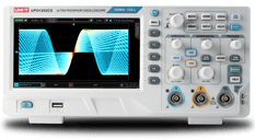
It's important to note that when using multiple channels simultaneously, the sampling rate will be evenly divided, which is known as interleaved mode. In this mode, the sampling rate can drop to 500MSa/s per channel when two channels are turned on, increasing the risk of missing signal details. However, the UNI-T UPO1000CS series oscilloscopes use a non-interleaved mode, maintaining a sampling rate of 1GSa/s per channel when all channels are turned on, ensuring high-quality testing that meets your R&D needs.
3. CHANNEL
An oscilloscope usually comes with either 2 or 4 analog channels, and the number of channels determines how many signals you can observe at the same time. In some cases, you may need more than 2 channels for tasks like BUS timing tests or multi-signal clock synchronization. Multi-channel oscilloscopes can also communicate between any two channels, making R&D testing more flexible and convenient. However, they can be more expensive, so it's important to choose the appropriate number of channels based on your current and future project needs when selecting an oscilloscope.
Keep in mind that some scopes may have a lower sampling rate when multiple channels are in use. This is an important factor to consider when selecting a scope.
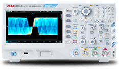
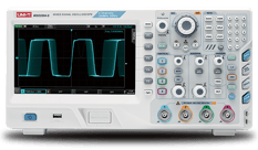
The MSO/UPO2000 series oscilloscopes are available in both 2 and 4 channel models. The "Multi-Scopes" feature supports multi-channel independent trigger fluorescence display, making it possible to test multiple signals at the same time. It also allows for simultaneous triggering of several independent signals, which helps engineers efficiently complete testing tasks.


4. Waveform Capture Rate


The speed at which an oscilloscope acquires waveforms is known as the waveform capture rate. A dead zone exists during the digital oscilloscope's waveform acquisition process. Increasing the waveform capture rate can significantly reduce dead time. During the dead time between two acquisitions, abnormal signals may go undetected. Therefore, selecting a scope with a higher waveform capture rate is critical for minimizing dead zones.
The UPO1000CS and MSO/UPO2000 series are ideal options as they have a "Fast Acquire" feature that enables waveform acquisition rates of 500,000 wfms/s and 1,000,000 wfms/s, respectively.
5. Memory Depth
The memory depth of an oscilloscope refers to the number of waveform points it can store for one acquisition. A larger memory depth is desirable if you want to capture more detailed information. The memory depth is determined by the recording time and sampling rate.
To achieve a "Single Shot Acquisition" with a memory depth of 4 Mpts, you need to sample the signal at 1 GSa/s, which will allow you to store 4 ms of signal data. For an oscilloscope with a memory depth of 1 Mpts, you can store 1 ms of waveform data at the same sampling rate.
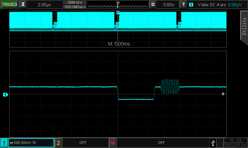
UNI-T UPO1000CS and MSO2000 series oscilloscopes offer independent memory depths of 56Mpts per channel, which is suitable for working with multiple channels simultaneously. This ensures sufficient memory depth to store more waveform points and display more waveform dynamics in a single acquisition, making it ideal for dealing with complex waveforms.
6. Triggering


The trigger function on an oscilloscope determines when data collection begins and the waveform is displayed. Digital oscilloscopes offer both pre-triggered and post-triggered waveforms. Triggering ensures a stable display of the waveform, allowing for quick identification of specific sections of a complex waveform.
Although all oscilloscopes have an edge trigger function, it may not be sufficient when dealing with complex waveforms. For example, edge triggering can produce an aliased waveform display when measuring PRBS codes or multi-edge signals. To complete testing tasks in such cases, advanced triggering functions are necessary.
UNI-T oscilloscopes come with a range of trigger functions including edge, pulse width, video, slope, runt, over amplitude pulse, delay, timeout, duration, setup/hold, Nth edge, and pattern triggers. In addition, the UPO1000CS and MSO/UPO2000 series scopes also support BUS triggers such as RS232, I2C, SPI, CAN, and LIN. With the Multi-Scopes function, multiple channels can be independently triggered. The MSO/UPO2000 series also features a touch screen and convenient area trigger function. Depending on the characteristics of the measured signal, engineers can select from a variety of trigger modes to achieve stable and fast triggering...
7. Automated Measurement
To speed up the waveform analysis, there are a variety of automated measurement parameters in the scopes. Use these parameters properly will improve the measurement efficiency. Automated parameter measurements help engineers to compete the test tasks faster. What’s better it ensures more accurate test results than cursor measurements.
In general, oscilloscopes come with basic measurement parameters such as amplitude, period, frequency, and rise/fall time. UNI-T oscilloscopes provide a total of 36 measurement parameters, including Max, Min, High, Low, Ampl, Pk-Pk, Middle, Mean, Cycmean, RMS, CycRMS, AC RMS, Period, Freq, Rise, Fall, RiseDelay, FallDelay, +Width, -Width, FRFR, FRFF, FFFR, FFFF, FRLF, FRLR, FFLR, FFLF, +Duty, -Duty, Area, CycArea, Oversht, Presht, Phase, Pulse, which meet your various R&D needs.
In addition, the channel operation of UNIT oscilloscope also provides functions such as basic operation, digital filtering, FFT, and advanced operation. The required test parameters can be edited and measured by the oscilloscope. For example, we can obtain the power value by multiplying the voltage and current when using the channel multiplication function. The channel subtraction function can be used for differential measurement. The enhanced FFT capability also serves the function of spectrum analysis..


8. Advanced Function
On top of the above factors to consider, be sure to base on your test requirements to choose the right scope. Also, a good software would be a handy tool for you to complete your test tasks.
BUS Analysis
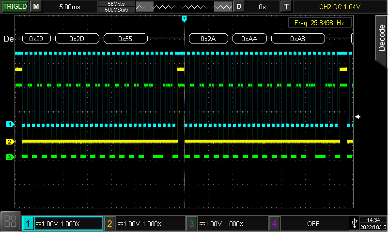
BUS analysis for embedded system, automobile control system is a common test scenario. The BUS triggering and analysis functions allows you to perform pattern analysis while analyzing the quality of the BUS signal easily and quickly.
UPO1000CS and MSO/UPO2000 series oscilloscopes with full hardware real-time decoding feature, make an accurate, efficient, and fast decoding and analysis process possible.
Logic analysis
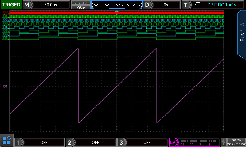
The digital channels equipped with oscilloscope can be used to automatic control system, complex digital system, debugging and fault diagnosis. With the logic analysis function, you don’t need a logic analyzer to visualize the pattern type of each channel. Logic analysis is commonly used in digital chip testing, interface testing, data protocol testing and so on.
MSO2000 series comes with 16 digital channels is a good choice for you. with options. You may also use the UPO2000 series for logical analysis.
FFT analysis
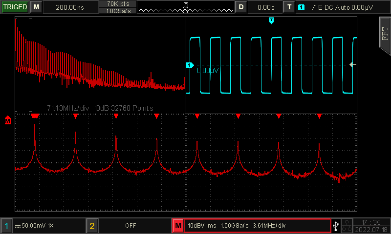
FTT serves the function of spectrum analysis. Select enhanced FFT analysis with better resolution if you expect a more accurate measurement.
UPO1000CS and MSO/UPO2000 series are equipped with the enhanced FFT which can set frequency range, detection mode, mark points, etc. There are also handy features like waterfall diagram and split screen. With 1Mpts and 4Mpts resolution respectively, the scope displays the frequency domain curve in detail.
Built-in signal generators
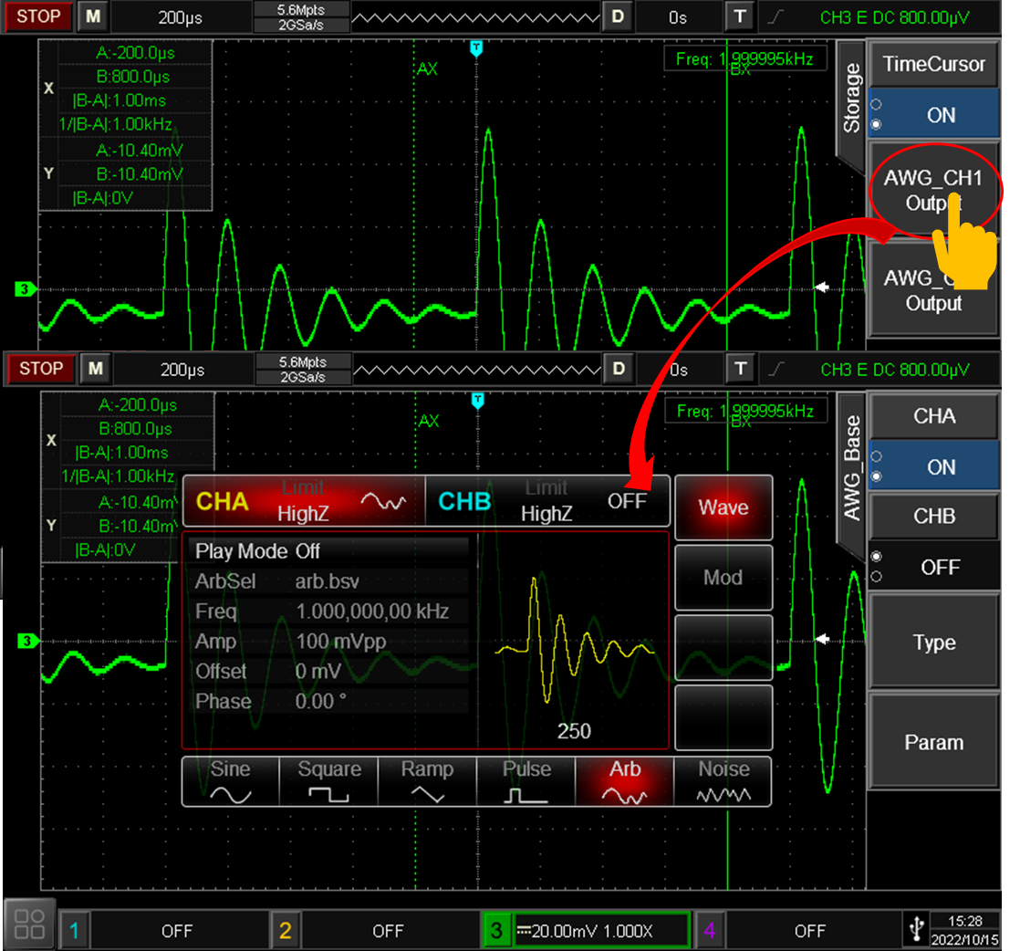
To complete the circuit debugging task, we need an oscilloscope, and most likely waveform generator as well. When using the oscilloscope equipped with built-in signal generator will not only reduce the cost of purchasing the instrument, but also save the lab space. Thus, a multiple function instrument is more and more popular in the T&M industry.
MSO2000-S series are equipped with a built-in dual-channel 250MSa/s sampling rate function arbitrary waveform signal generator. The maximum frequency output of sine wave is 50MHz. It can not only meet the demand of conventional signal source, but also realize the arbitrary wave function of oscilloscope waveform, which makes development, debugging, test and measurement a lot more convenient.
Bode plot for loop analysis
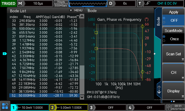
A Bode plot is simply a plot of magnitude and phase of a transfer function as frequency varies., which is mainly used for the system stability evaluation. It is expensive to purchase the loop analysis instrument separately. The built-in signal generator use the algorithm for loop analysis.
The UNI-T MSO2000-S series, with optional bode plot function is an ideal multiple function scope for you.,
Bode plot analysis is mainly used in switching power supply, closed-loop negative feedback system stability, open-loop system frequency response and other fields. You can choose according to your project’s requirements.
Voltmeter
The voltmeters, partially serve the functions of the digital multimeter in the oscilloscope, which makes circuit analysis and device measurement more flexible.
Frequency meter

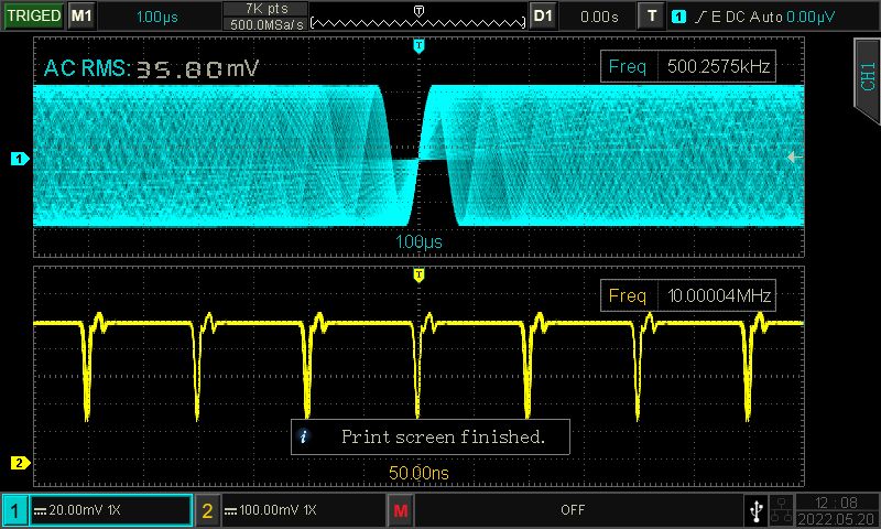
Oscilloscopes with frequency meter function makes high precision frequency measurement possible. UPO1000CS, MSO/UPO2000 series oscilloscopes are equipped with multi-channel 7-bit frequency meter. All channels can be measured simultaneously and provide frequency with 7-bit accuracy. The multifunctional oscilloscopes meet a variety of needs, save cost and space.
9. Expansion
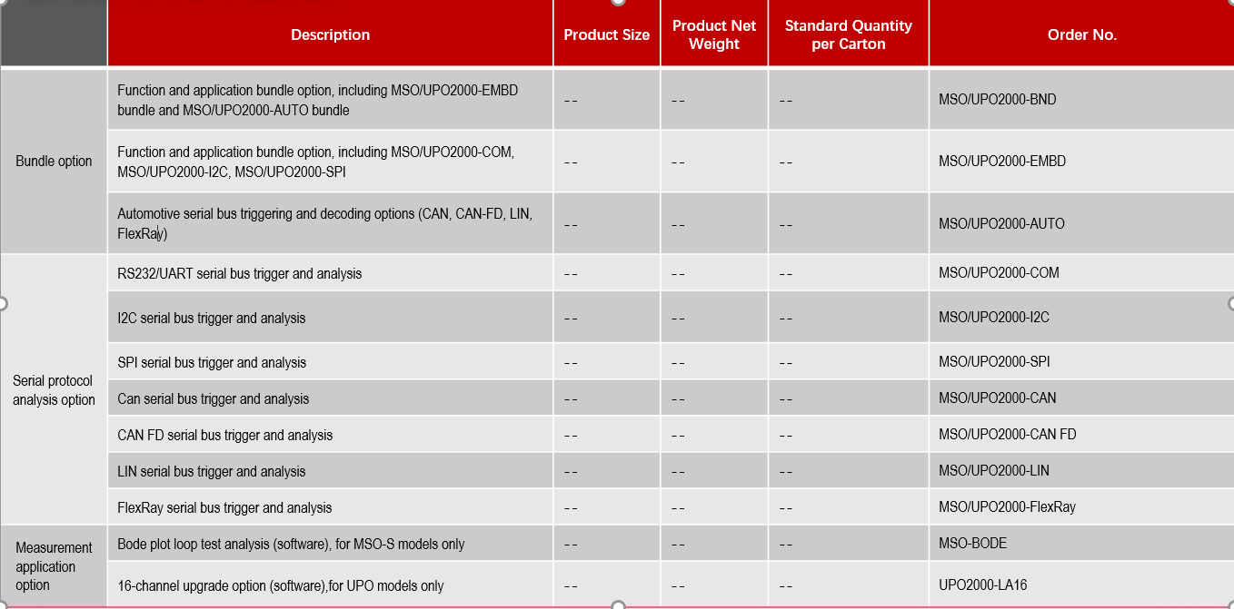
From time to time, your existing oscilloscope does not fulfill the test requirements of a new project, you may consider getting another scope for a specific new feature. Having an upgradable scope would be ideal in such cases. The UPO1000CS series and MSO/UPO2000 series offer a variety of options, including bus decoding functions, digital channel options, and bode plot options for the MSO/UPO2000 series. You can easily expand the capabilities of your scope to meet your new testing requirements.
10. Connectivity
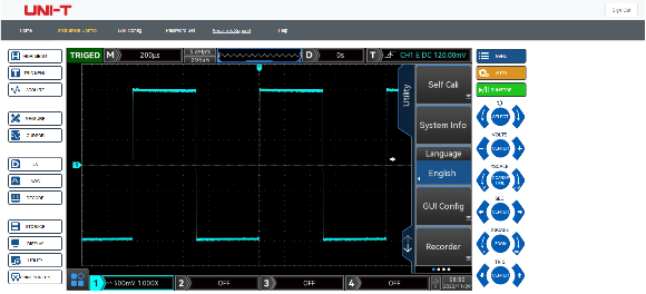
There are different ways to connect an oscilloscope to other devices, such as a PC, using LAN or USB ports, and even other interfaces. The scope may also have a VGA port to connect to an external monitor. By connecting to a computer via USB, engineers can easily save waveform files and screenshots for remote analysis, which is especially helpful for remote work.
UNI-T provides its own software that allows for remote control, fast saving, and quick analysis. The software also supports the SCPI protocol and provides a programming guide for automatic test platform setup. The MSO/UPO2000 series and UPO1000CS series offer web page access, which adds to the flexibility of your testing work.
Considering the above 10 factors can assist you in selecting a cost-effective oscilloscope. Should you have any questions about using our products, please don't hesitate to contact the UNI-Trend team. We are always available to provide further assistance with your testing tasks.
